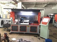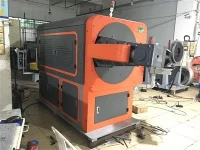


CNC 3D Wire Bending Machine
The CNC 3D Wire Bending Machine forms metal wire into three-dimensional components through programmed feeding, bending, lifting and cutting. Its 5-axis configuration allows bends to be positioned in different directions and planes, making it suitable for brackets, frames, hooks, supports and other multi-bend wire parts.
The specified working range is Ø3–Ø10 mm for wire with tensile strength up to 500 N/mm², including Q195 and Q235. Maximum wire feeding speed is 90 m/min, while the automatic wire feeder supports a maximum wire load of 3,000 kg.
For machine selection, wire diameter should be considered together with material strength, bend radius, part dimensions and required tolerance.
Product Advantages
5-Axis 3D Forming
Five controlled axes coordinate the feeding and forming movements, allowing the wire to be bent across different planes. This configuration is suitable for three-dimensional parts that require multiple directional bends rather than a flat 2D profile.
The maximum arm length is 950 mm, defining the available working range for suitable part geometries.
Ø3–Ø10 mm Wire Processing
The specified wire range is Ø3–Ø10 mm, with tensile strength up to 500 N/mm². Q195 and Q235 are typical applicable low-carbon steel wire grades.
Material strength affects the forming force required during bending. High-strength or special wire should therefore be evaluated separately before production.
Separate Drive Systems
Dedicated motors are provided for the main machine movements:
|
Function |
Motor Power |
|
Wire feeding |
4.5 kW |
|
Arm movement |
2.7 kW |
|
Bending |
2.7 kW |
|
Lifting |
1.0 kW |
|
Cutting |
1.8 kW |
The separate drive arrangement allows feeding, bending, lifting and cutting movements to operate according to the programmed forming sequence.
Maximum Wire Feeding Speed of 90 m/min
The maximum wire feeding speed is 90 m/min.
This specification refers to wire movement through the feeding system, not guaranteed finished-part output. Actual cycle time depends on wire diameter, material, number of bends, bending angles, part geometry and cutting operations.
Automatic Wire Feeder with 3,000 kg Capacity
The automatic wire feeder supports a maximum wire load of 3,000 kg, with a Ø1,800 mm disc and a 3 kW motor.
This capacity can reduce the frequency of manual wire loading during longer production runs. Actual running time between coil changes depends on wire diameter and coil weight.
Controlled Wire Feeding
The specified wire feeding accuracy is 300 mm ±0.1 mm.
This is a feeding-system specification at the stated distance. It should not be interpreted as a finished-part tolerance, since final dimensions are also affected by wire straightness, material consistency, tooling, bend radius, springback and machine adjustment.
Technical Specifications
|
Specification |
Detailed Parameter |
|
Equipment Type |
CNC 3D Wire Bending Machine |
|
Wire Diameter |
Ø3–Ø10 mm |
|
Applicable Wire Strength |
Tensile strength ≤500 N/mm² |
|
Typical Materials |
Q195, Q235 and other suitable wire materials |
|
Maximum Arm Length |
950 mm |
|
Number of Controlled Axes |
5-axis |
|
Wire Feeding Motor |
4.5 kW |
|
Arm Motor |
2.7 kW |
|
Bending Motor |
2.7 kW |
|
Lifting Motor |
1.0 kW |
|
Cutter Motor |
1.8 kW |
|
Maximum Wire Feeding Speed |
90 m/min |
|
Wire Feeding Accuracy |
300 mm ±0.1 mm |
|
Automatic Wire Feeder Capacity |
Max. 3,000 kg |
|
Automatic Wire Feeder Disc Diameter |
Ø1,800 mm |
|
Automatic Wire Feeder Motor |
3 kW |
|
Main Machine Voltage |
AC 380 V ±20 V |
|
Main Machine Weight |
Approx. 2,800 kg |
|
Main Machine Dimensions |
3,800 × 2,000 × 1,900 mm (L × W × H) |
|
Automatic Wire Feeder Weight |
Approx. 1,000 kg |
|
Automatic Wire Feeder Dimensions |
1,800 × 1,800 × 1,650 mm (L × W × H) |
Application Scenarios
Automotive Wire Components
Suitable for brackets, retaining parts, supports, clips and other formed-wire components requiring multiple directional bends.
Furniture and Hardware
Typical applications include wire frames, hooks, racks, supports and other formed-wire hardware components.
Display and Retail Equipment
Suitable for display hooks, holders, frames and support structures manufactured from steel wire.
Industrial Wire Components
Applications include brackets, handles, guards, supports and customized wire parts produced according to technical drawings.
Custom Wire Components
Suitable for manufacturers producing customized wire components from customer drawings or samples. The forming sequence and tooling can be evaluated according to the actual part geometry and wire condition.
The final application range depends on wire diameter, material strength, bend radius, part dimensions and tooling requirements.
Packaging & Delivery
The machine is packed in standard export wooden cases for international transportation. The packaging method is intended to protect the equipment during loading, handling and shipment.
Buyers can arrange transportation through their own nominated freight forwarder. The shipping information can be coordinated directly with the appointed forwarder.
A forwarding service can also be arranged for buyers who require assistance with shipment coordination.
Typical delivery time is 6–10 days after receipt of deposit, subject to the confirmed machine configuration and production schedule.
Sea or air transportation can be arranged according to the destination, delivery requirements and shipment conditions.
FAQ
Q: What wire diameter can this machine process?
A: The specified range is Ø3–Ø10 mm for wire with tensile strength up to 500 N/mm². Actual suitability depends on the material condition and finished-part geometry.
Q: Can it process Q195 and Q235 wire?
A: Yes. Q195 and Q235 are typical materials within the specified application range when the actual wire meets the stated tensile-strength requirement.
Q: Is 90 m/min the finished-part production speed?
A: No. 90 m/min is the maximum wire feeding speed. Actual production output depends on the complete forming cycle, including feeding, bending, lifting and cutting.
Q: Does 300 mm ±0.1 mm mean the finished part has ±0.1 mm tolerance?
A: No. This specification refers to feeding accuracy over a 300 mm distance. Finished-part tolerance must be evaluated separately according to wire properties, tooling, bend radius, springback and part geometry.
Q: Can the machine process customized 3D wire parts?
A: Yes, provided the wire and finished-part geometry fall within the machine's working range. A finished-part drawing or sample is recommended for evaluating the forming sequence and tooling requirements.
Q: Can my actual wire be tested before ordering?
A: For new or non-standard applications, sample bending can be used to evaluate wire feeding, forming sequence, tooling compatibility and finished-part requirements before confirming the machine configuration.
Request a Technical Evaluation
Send your wire specification and finished-part drawing or sample.
For a more accurate evaluation, include the wire diameter, material grade, tensile strength or hardness, part dimensions, required tolerance and production quantity. The suitable machine configuration and tooling can then be assessed according to the actual application before quotation.
Hot Tags: 3d cnc wire bending machine, China 3d cnc wire bending machine manufacturers, suppliers, factory, 2D Wire Bending Machine for Automotive Parts